BuildCAD AI

Hand-crank gearbox, customizable: 3:1 reduction on 5 mm steel pins

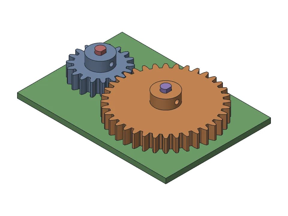
A small 3:1 reduction you turn by hand, for a demo, a winch or a toy. A 12 tooth input gear with a crank drives a 36 tooth output wheel. Both turn on 5 mm steel pins pressed into an 82 x 63 mm base plate with four countersunk M4 holes. Set the module (1.5 to 2.5), the input teeth (12 to 20, the wheel always gets 3 times as many), the gear width, the pin diameter, the crank length and the knob height.

Customize Change it with AIFree STL, 3MF and STEP, no accountMeasured on the model

Parameters

Gear module (tooth size)mm
Input gear teeth (wheel gets 3x)
Gear thicknessmm
Steel pin diametermm
Crank length (pin to knob)mm
Knob heightmm

Sliders and downloads are free. Changes by the AI designer use credits like any design; new accounts start with free ones.

All four parts print without supports: the plate and gears flat, the crank with its hex socket on the bed. The gears have 5.4 mm bores on the 5 mm pins and the plate holes are 5.1 mm for a press fit, so try a pin in the plate first. Nothing holds the gears down on their pins, and the crank is a friction fit on a hex hub, so glue it. The free turning was checked by a motion simulation on the model, not on a print.

Parameters

Every slider in the viewer above, with the range the model accepts. The model rebuilds valid at both ends of each range.

ParameterRangeDefaultWhat it changes
Gear module (tooth size)1.5 to 2.5 mm1.5 mmTooth size for both gears. A larger module gives stronger teeth and a bigger box; the ratio stays 3:1.
Input gear teeth (wheel gets 3x)12 to 2012Teeth on the input gear under the crank. The output wheel always gets 3 times as many, so the box grows with it.
Gear thickness4 to 12 mm6 mmThickness of both gears. Thicker gears carry more torque, and the pins to buy get longer.
Steel pin diameter4 to 6 mm5 mmDiameter of the steel pins you buy. The gear bores and the plate holes follow it.
Crank length (pin to knob)20 to 60 mm28 mmDistance from the input pin to the knob. A longer crank takes less force to turn.
Knob height8 to 30 mm15 mmHeight of the knob you hold. Make it taller for a full grip.

Proof: measured on the model

What the design must satisfy and what our CAD engine measured on the model at the default values. Only measured values are shown here; nothing on this page has been printed by us yet.

RequirementWantedMeasured
Distance between the two pins36 mm: module 1.5 x (12 + 36) / 236 mm
Play between the gear teeth0.15 mm per flank (0.3 mm backlash)0.15 mm
Gear bore on the 5 mm pin5.4 mm (0.2 mm play per side)5.4 mm
Press-fit holes for the steel pins in the plate (5.1 mm)2 holes2
Gap between the crank arm and the wheel1 mm1 mm
Output wheel tip diameter (36 teeth)about 57 mm, less the backlash trim56.859 mm
  • plate: valid solid, one body, 82 x 63 x 4.6 mm, fits a 256 x 256 x 256 mm printer; overhangs: 0.0% of surface would need support.
  • pinion: valid solid, one body, 21 x 21 x 10.5 mm, fits a 256 x 256 x 256 mm printer; overhangs: 0.0% of surface would need support.
  • wheel: valid solid, one body, 56.9 x 56.9 x 6 mm, fits a 256 x 256 x 256 mm printer; overhangs: 0.0% of surface would need support.
  • crank: valid solid, one body, 41.9 x 15.9 x 20 mm, fits a 256 x 256 x 256 mm printer; overhangs: 4.6% of surface would need support.
  • Motion: 2 moving joints swept through their range with every pose checked for collisions, no problem reported at the defaults. See the Joints tab in the viewer.

Print notes

Orientation
The plate, the input gear and the wheel lie flat as modelled; the crank prints arm down with its hex socket on the bed and the knob up.
Supports
None (the roof of the crank's hex socket is one bridge of about 11 mm)
Material
PLA or PETG
Layer height
0.2 mm
Settings
4 walls on the gears and the crank, so the bores and the hex hub are solid
Hardware
1 x 5 mm steel pin, 14 mm long (input gear); 1 x 5 mm steel pin, 10 mm long (output wheel); 4 x M4 countersunk screws, if you fix the plate down
Time and filament
About 1 h 25 min and 30 g at the default size: a rough estimate from the model's volume and surface (PLA, 15% infill, about 1 mm of walls, 0.2 mm layers), not a slicer.
  • Press the pins in until they bottom out in the blind holes. The 5.1 mm holes assume your printer makes holes slightly small; if a pin will not go in, drill the hole to 5.0 mm.
  • Slide the wheel on first, then the input gear with its teeth meshed, then push the crank onto the hex hub with a dab of glue.
  • The gears are held down by gravity only. To use the gearbox on its side, glue a washer or a printed cap on each pin end.
  • The 12 tooth input gear has slightly thin tooth roots (undercut). For more load, raise the module or the gear width.

How it was designed

Designed with buildcad's AI agent, checked by the buildcad team. This is the request it started from and an edited account of what it did (more on how text to CAD works).

The request

A small hand-crank gearbox, 3:1 reduction, both gears on 5 mm steel pins in a base plate, with a crank handle on the input gear. It should print without supports and turn freely.

  1. 1

    Sizes and checks first

    The agent picked module 1.5 with a 12 tooth input gear and a 36 tooth wheel for the 3:1 ratio, 6 mm wide. Its checks: tip diameters of about 21 and 57 mm, two 5.1 mm press-fit holes for the pins, a 5.4 mm free-running bore, 0.05 to 0.3 mm between the teeth and at least 0.5 mm under the crank.

  2. 2

    First build: the gears sat on the plate

    All seven checks passed, but the motion check, which turned the crank 3 full turns, found both gears touching the plate (0 mm gap) and only 0.1 mm between the teeth. Both would likely fuse or bind when printed.

  3. 3

    More room to turn

    The agent lifted the gears 0.3 mm above the plate bosses and raised the backlash to 0.3 mm. The next 3 turn sweep found no collisions: 0.15 mm per flank at the closest point, 0.3 mm under the gears, 0.19 mm between each bore and its pin and 1 mm between the crank and the wheel.

  4. 4

    Slider extremes and assembly steps

    The slider sweep rebuilt every extreme without errors. The assembly check also slides each of the 4 steps (pins, wheel, input gear, crank) in from above and finds each one clear of the parts placed before it.

  5. 5

    What it left to the maker

    Its reply points out the undercut on the 12 tooth gear, that nothing holds the gears down on their pins and that the crank needs glue. It did not print the gearbox, so the press fit of the pins is the first thing to try.

One run of the agent: 3 min 5 s, about $0.34 of model time at list price (claude-sonnet-5-5). The model code behind this page is the code it wrote, unchanged.
Change it with AI

Set the sliders, then press Change it with AI: a copy goes to your designs at those sizes and the designer opens with a suggested change you can edit. Its changes use credits like any design; new accounts start with free ones.