BuildCAD AI

Spur gear pair, customizable: module, teeth and D-shaft hub

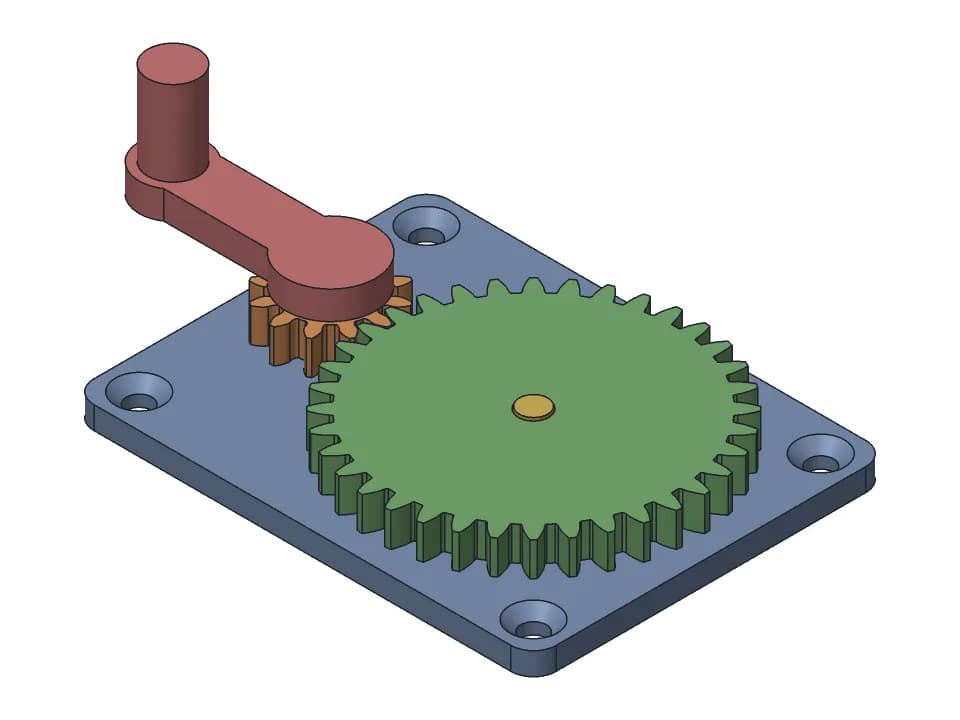
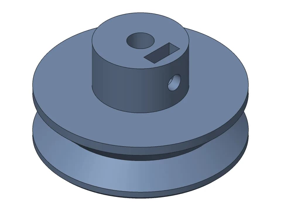
Two spur gears for a small 3D printed drive: an 18 tooth pinion and a 36 tooth wheel, module 1.5 with an 8 mm face, for a 2:1 reduction. Each has a 14 mm hub with a D-shaped bore for a 5 mm D-shaft and a radial M3 set screw hole that lands on the flat. Set the module (1 to 3 mm), the tooth counts (12 to 60 and 12 to 90), the face width, and the shaft, bore and hub sizes to match your motor or axle.

Customize Change it with AIFree STL, 3MF and STEP, no accountMeasured on the model

Parameters

Modulemm
Pinion teeth
Wheel teeth
Face widthmm
Backlashmm
Shaft diametermm
D-shaft across flat (flat to opposite side)mm
Bore clearancemm
Hub diametermm
Hub length above gearmm
M3 set screw hole (2.6 = tapped by screw)mm

Sliders and downloads are free. Changes by the AI designer use credits like any design; new accounts start with free ones.

Both gears print flat, hub up, with no supports. The bore is 5.2 mm round and 4.7 mm across the flat (0.2 mm play), measured on the model below. Check your shaft's flat with calipers and print the small gear first to try the bore and the set screw. The teeth are plain 20 degree involute with 0.2 mm backlash. The viewer shows the pair meshed on stand-in shafts 40.5 mm apart at the defaults, the spacing to mount yours at, and turning it sweeps the teeth for collisions.

Parameters

Every slider in the viewer above, with the range the model accepts. The model rebuilds valid at both ends of each range.

ParameterRangeDefaultWhat it changes
Module1 to 3 mm1.5 mmTooth size, shared by both gears. It scales the whole pair: the tip diameter is module x (teeth + 2).
Pinion teeth12 to 6018Tooth count of the small gear (pinion). The ratio is the wheel's teeth divided by these.
Wheel teeth12 to 9036Tooth count of the large gear (wheel). 36 with an 18 tooth pinion gives 2:1.
Face width4 to 20 mm8 mmThickness of the toothed part of both gears. Wider teeth carry more load.
Backlash0 to 0.6 mm0.2 mmPlay trimmed from the tooth flanks so the pair does not bind. Raise it if your printer makes teeth slightly fat.
Shaft diameter3 to 10 mm5 mmNominal diameter of your shaft. The round side of the bore is this plus the bore clearance.
D-shaft across flat (flat to opposite side)2.5 to 9.5 mm4.5 mmYour D-shaft measured from the flat to the opposite side, with calipers. Set it equal to the shaft diameter for a plain round bore.
Bore clearance0 to 0.5 mm0.2 mmExtra room added to the bore, both on the diameter and across the flat. Raise it if the shaft will not go in.
Hub diameter8 to 30 mm14 mmOutside diameter of the hub that carries the set screw. It keeps at least a 3 mm wall around the bore, and on small gears it is capped to stay inside the tooth roots.
Hub length above gear3 to 20 mm6 mmHow far the hub stands above the gear face. The set screw sits at its mid height, and a longer hub grips more of the shaft.
M3 set screw hole (2.6 = tapped by screw)2.2 to 3.4 mm2.6 mmDiameter of the radial set screw hole. At 2.6 mm an M3 screw cuts its own thread; larger values give a looser hole.

Proof: measured on the model

What the design must satisfy and what our CAD engine measured on the model at the default values. Only measured values are shown here; nothing on this page has been printed by us yet.

RequirementWantedMeasured
Pinion tip diameter (18 teeth, module 1.5)30 mm: module x (18 + 2)30 mm
Wheel tip diameter (36 teeth, module 1.5)57 mm: module x (36 + 2)57 mm
Bore diameter on the round side5.2 mm (5 mm shaft + 0.2 mm clearance)5.2 mm
Bore across the flat, for the D-shaft4.7 mm (4.5 mm flat + 0.2 mm clearance)4.7 mm
M3 set screw holes (2.6 mm), one in each hub2 holes2
Height of each gear, face plus hub14 mm (8 mm face + 6 mm hub)14 mm
  • pinion: valid solid, one body, 30 x 29.7 x 14 mm, fits a 256 x 256 x 256 mm printer; overhangs: 0.3% of surface would need support.
  • wheel: valid solid, one body, 56.9 x 56.9 x 14 mm, fits a 256 x 256 x 256 mm printer; overhangs: 0.1% of surface would need support.
  • Motion: 2 moving joints swept through their range with every pose checked for collisions, no problem reported at the defaults. See the Joints tab in the viewer.

Print notes

Orientation
Both gears lie flat with the hub up (Print plate in the viewer). The viewer shows them meshed by default, on stand-in D-shafts and a stand-in frame plate that are not printed.
Supports
None
Material
PLA for light duty, PETG if the gears run for long periods
Layer height
0.2 mm
Settings
4 walls, so the teeth and the hub around the bore and set screw are solid
Hardware
2 x M3 set screws (one per hub); 2 x 5 mm D-shafts, 4.5 mm across the flat (or your own shafts, with the sliders set to match)
Time and filament
About 45 min and 16 g at the default size: a rough estimate from the model's volume and surface (PLA, 15% infill, about 1 mm of walls, 0.2 mm layers), not a slicer.
  • Print the pinion first and try it on your shaft. The 0.2 mm bore play is the model's assumption: raise Bore clearance if the shaft is tight.
  • The 2.6 mm hole is sized for an M3 set screw to cut its own thread. Tighten it onto the flat of the shaft.
  • Mount the shafts module x (pinion teeth + wheel teeth) / 2 apart: 40.5 mm at the defaults, the spacing the mesh is checked at in the viewer.

How it was designed

Designed with buildcad's AI agent, checked by the buildcad team. This is the request it started from and an edited account of what it did (more on how text to CAD works).

The request

A pair of spur gears for a 3D printed project: module 1.5, 18 and 36 teeth, 8 mm face width, each with a hub and an M3 set screw boss for a 5 mm D-shaft. Make module, teeth, bore and hub size adjustable.

  1. 1

    It wrote the checks first

    The agent listed what had to be true before modelling: tip diameters of module x (teeth + 2), so 30 mm for the 18 tooth pinion and 57 mm for the 36 tooth wheel less the backlash trim, 14 mm tall parts (8 mm face plus 6 mm hub), one 2.6 mm M3 set screw hole per hub and a gap between the two parts on the bed.

  2. 2

    First build: right sizes, two slider ends broke

    The first model used a standard 20 degree involute tooth, trimmed 0.1 mm per flank for 0.2 mm of backlash. Every check passed (29.8 and 56.8 mm tips), but the slider sweep failed at 60 teeth on the pinion and 120 on the wheel: the flank trim could not be computed there.

  3. 3

    A fallback for the tooth trim

    The agent tested the trim on its own: at 60 teeth a second offset method worked, at 120 neither did. It made the model try both methods, which fixed 60 teeth, but the 120 tooth wheel still came out invalid.

  4. 4

    It capped the wheel at 90 teeth

    It lowered the wheel's maximum to 90 teeth. The sweep then rebuilt all 22 slider extremes as one valid body per part, with the checks unchanged at the defaults.

  5. 5

    What it left to the maker

    Its reply asks you to measure your shaft's flat, place the shafts 40.5 mm apart and try the bore and set screw on the small gear before printing the large one. It did not check the mesh, because the gears are laid out side by side for printing.

  6. 6

    Our change

    We made the pair an assembly. The teeth now come from buildcad's gear pair helper, which meshes and phases the two gears with the same module, tooth counts, face width and backlash; the hubs, D bores and set screw holes are added as before. The viewer turns them on stand-in D-shafts and a stand-in frame plate (not printed), and the print plate lays both gears flat, hub up.

One run of the agent: 2 min 5 s, about $0.18 of model time at list price (claude-sonnet-5-5). We changed the code afterwards, as described in the last step.
Change it with AI

Set the sliders, then press Change it with AI: a copy goes to your designs at those sizes and the designer opens with a suggested change you can edit. Its changes use credits like any design; new accounts start with free ones.