BuildCAD AI

Raspberry Pi 5 case, customizable: vented lid and adjustable headroom

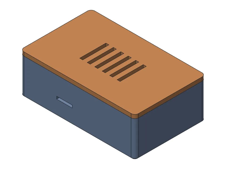
A two-part case for a Raspberry Pi 5: a base of 95.6 x 63.6 x 25.9 mm and a vented lid. The board sits on four screw bosses at its 58 x 49 mm mounting holes. The walls have openings for USB-C power, both micro-HDMI, Ethernet, the four USB-A ports, the power button and the microSD card, and the lid has a GPIO opening you can turn off. Set the space above the board (17 to 30 mm), the standoff, the room around plugs and the vent slots.

Customize Change it with AIFree STL, 3MF and STEP, no accountMeasured on the model

Parameters

Floor thicknessmm
Board standoff heightmm
Space above the boardmm
Lid thicknessmm
Extra room around cable plugs (front/left)mm
Vent slots
Vent slot widthmm
Vent slot lengthmm

Sliders and downloads are free. Changes by the AI designer use credits like any design; new accounts start with free ones.

Both parts print without supports, the lid upside down. Port positions come from the Raspberry Pi 5 mechanical drawing, but the board thickness and connector heights are Pi 4 values, and the microSD and power button positions are the least certain. The fit was checked against a stand-in board model, not a real Pi 5, so print the front wall first. There are no openings for the camera and display connectors, PCIe or a cooler fan.

Parameters

Every slider in the viewer above, with the range the model accepts. The model rebuilds valid at both ends of each range.

ParameterRangeDefaultWhat it changes
Floor thickness1.2 to 4 mm2 mmThickness of the base floor. Raise it for a stiffer bottom.
Board standoff height3 to 10 mm5 mmHeight of the board bosses above the floor. Raise it if you need room under the board, for example for a bottom-mounted part.
Space above the board17 to 30 mm17.5 mmSpace between the top of the board and the lid. Raise it for a HAT, a heatsink or taller connectors than assumed.
Lid thickness2 to 4 mm2.4 mmThickness of the lid plate. A thicker lid is stiffer and gives the countersunk screws more to bite on.
Extra room around cable plugs (front/left)0.5 to 4 mm2 mmExtra room around the USB-C and micro-HDMI openings in the front wall. Raise it for bulky cable plugs.
Ventilation slots in lidOn or offOnCuts ventilation slots in the lid over the middle of the board. Turn it off for a closed lid.
Vent slots3 to 1412Number of vent slots in the lid.
Vent slot width1.6 to 4 mm2.4 mmWidth of each vent slot. Narrow slots keep fingers and dust out better.
Vent slot length10 to 40 mm30 mmLength of each vent slot, front to back.
GPIO opening in lidOn or offOnCuts a 54 x 6 mm opening in the lid above the GPIO header so you can plug in jumper wires. Turn it off for a closed lid.

Proof: measured on the model

What the design must satisfy and what our CAD engine measured on the model at the default values. Only measured values are shown here; nothing on this page has been printed by us yet.

RequirementWantedMeasured
Board screw bosses, spacing along the board58 mm (Pi 5 hole pattern 58 x 49 mm)58 mm
Board screw bosses, spacing across the board49 mm49 mm
Screw pilot holes of 2.2 mm for M2.5 self-tapping screws (4 board, 4 lid)8 holes8
Top of the board bosses above the bed7 mm (2 mm floor and 5 mm standoff)7 mm
Play between the lid lip and the base walls, per side0.2 mm0.2 mm
Width of the USB-C power opening13 mm (9 mm plus 2 mm of plug room per side)13 mm
  • base: valid solid, one body, 95.6 x 63.6 x 25.9 mm, fits a 256 x 256 x 256 mm printer; overhangs: 1.2% of surface would need support.
  • lid: valid solid, one body, 95.6 x 63.6 x 5.4 mm, fits a 256 x 256 x 256 mm printer; overhangs: 0.1% of surface would need support.

Print notes

Orientation
The base stands on its floor; the lid lies upside down, plate on the bed and lip pointing up (Print plate in the viewer, which shows the case closed by default).
Supports
None
Material
PETG or ASA if the Pi runs warm for long periods, PLA for light use
Layer height
0.2 mm
Hardware
4 x M2.5 self-tapping screws, 6 mm, for the board; 4 x M2.5 countersunk self-tapping screws, 10 mm, for the lid
Time and filament
About 2 h 15 min and 50 g at the default size: a rough estimate from the model's volume and surface (PLA, 15% infill, about 1 mm of walls, 0.2 mm layers), not a slicer.
  • Print only the front wall first and try your USB-C and micro-HDMI cables. The fit was checked on a stand-in board model, not a real Pi 5, and plug bodies vary.
  • The board thickness (1.4 mm) and the USB and Ethernet heights (16 and 13.5 mm) are Pi 4 values. If your connectors are taller, raise the space above the board.
  • The microSD and power button openings are the least certain positions. Check them on your board before the full print.
  • The lid lip is left off on the USB and Ethernet side so it cannot hit those housings. There are no openings for the camera or display ribbon connectors, PCIe or an active cooler fan.

How it was designed

Designed with buildcad's AI agent, checked by the buildcad team. This is the request it started from and an edited account of what it did (more on how text to CAD works).

The request

A two-part case for a Raspberry Pi 5 with openings for all ports, a vented lid, and screw bosses for the board's mounting holes.

  1. 1

    It read the board data first

    The agent loaded the Pi 5 entry of the parts library, taken from the Raspberry Pi mechanical drawing: an 85 x 56 mm board, four 2.7 mm holes in a 58 x 49 mm pattern, the connector positions on each edge, and a note that Ethernet and USB overhang the right edge by about 3 mm. The drawing gives no board thickness or connector heights, so it used Pi 4 values (1.4 mm, USB 16 mm, Ethernet 13.5 mm).

  2. 2

    First build

    The base and lid built as valid single bodies, with the eight 2.2 mm screw pilots it planned, four 2.9 mm lid holes and a base of 95.6 x 63.6 x 25.9 mm. Neither part needed supports.

  3. 3

    A stand-in board caught a collision

    The agent placed a simple board model with connector housings in the case. It overlapped the base by 1.13 mm: a plain rectangle with square corners reaches into the corner posts for the lid screws. Rebuilt with the board's 3 mm rounded corners and its mounting holes, the stand-in board cleared the base, and the lid sat 1.5 mm above it.

  4. 4

    It checked the lid and every opening

    Lifting the lid 2 mm showed a 0.2 mm gap between its lip and the walls, with no overlap when seated. Rays through each opening at mid height and at the connector top passed free for USB-C, both micro-HDMI, Ethernet, both USB stacks, the power button and the microSD slot. The slider sweep rebuilt all 16 extremes.

  5. 5

    What it left to the maker

    The agent's reply says it did not test-print the case, names the assumed heights and the uncertain microSD and power button positions, and suggests printing the front wall to check the plug fit.

  6. 6

    Our change

    We made the model an assembly: the lid sits on the walls where it is screwed down, so the viewer shows the closed case, and the print plate turns the lid upside down for the downloads. Both parts are otherwise unchanged.

One run of the agent: 5 min 5 s, about $0.68 of model time at list price (claude-sonnet-5-5). We changed the code afterwards, as described in the last step.