BuildCAD AI

ESP32 DevKitC enclosure, customizable: snap-on lid and USB opening

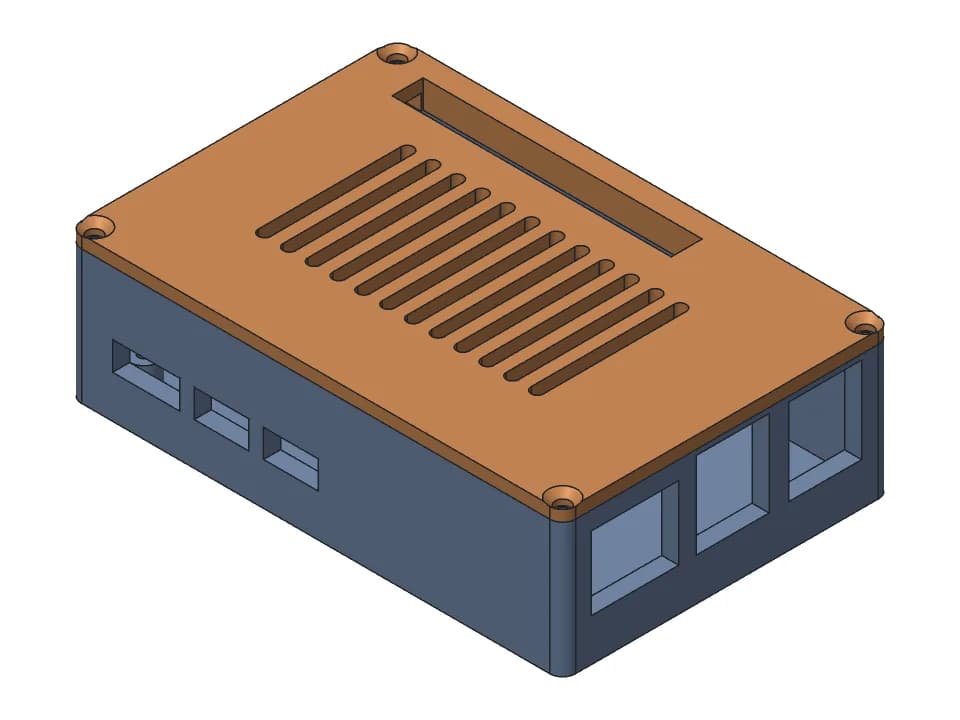
A two-part case for the ESP32-DevKitC V4 dev board, 61.3 x 37.9 x 21.1 mm outside with the lid on. The board lies pins down on two ribs between its header rows, 9 mm above the floor, and four small blocks stop it sliding sideways. A 12 x 7.5 mm end wall opening leaves the micro-USB port free. The lid has six vent slots and two snap arms that click into windows in the long walls. Set the space under and above the board and the USB opening size.

Customize Change it with AIFree STL, 3MF and STEP, no accountMeasured on the model

Parameters

Wall thicknessmm
Floor thicknessmm
Space under board (header pins)mm
Space above board (parts, wires)mm
USB opening widthmm
USB opening heightmm

Sliders and downloads are free. Changes by the AI designer use credits like any design; new accounts start with free ones.

Both parts print flat with no supports. The board outline comes from the Espressif drawing; the board thickness and the pin length are assumed, and the snap fit is checked on the model only. Measure how far your header pins stick out under the board and set the space under it. There are no cut-outs for the EN and BOOT buttons, and clone boards (30 or 38 pin, USB-C) differ, so measure yours.

Parameters

Every slider in the viewer above, with the range the model accepts. The model rebuilds valid at both ends of each range.

ParameterRangeDefaultWhat it changes
Wall thickness1.6 to 4 mm2 mmThickness of the side and end walls. The snap windows go through the long walls.
Floor thickness1.2 to 4 mm2 mmThickness of the base floor.
Space under board (header pins)3 to 14 mm9 mmSpace between the floor and the underside of the board, for the header pins. Set it to how far your pins stick out below the board; lower it for short pins or no headers.
Space above board (parts, wires)4 to 14 mm6.5 mmSpace between the top of the board and the lid. Raise it if you plug in tall parts or wires on top.
USB opening width9 to 20 mm12 mmWidth of the opening for the USB plug in the end wall. Raise it for a bulky plug.
USB opening height5 to 12 mm7.5 mmHeight of the opening for the USB plug, measured up from just below the top of the board. At the defaults it runs up to the rim and the lid closes it.
Vent slots in lidOn or offOnCuts six vent slots in the lid over the board. Turn it off for a closed lid.

Proof: measured on the model

What the design must satisfy and what our CAD engine measured on the model at the default values. Only measured values are shown here; nothing on this page has been printed by us yet.

RequirementWantedMeasured
Inside length, for the 48.26 mm board and its 6.04 mm antenna overhang57.3 mm (1.5 mm gap at each end)57.3 mm
Inside width, for the 27.94 mm board and the snap arms beside it33.94 mm (3 mm per side)33.94 mm
Space between the floor and the underside of the board, for the header pins9 mm (the slider)9 mm
Width of the USB opening in the end wall12 mm (the slider)12 mm
Bottom of the USB opening above the bed (top of the board at 12.6 mm)12.1 mm (0.5 mm below the top of the board)12.1 mm
Gap between the closed lid's snap arms and the board1 mm or more1.5 mm
  • base: valid solid, one body, 61.3 x 37.9 x 19.1 mm, fits a 256 x 256 x 256 mm printer; overhangs: 0.9% of surface would need support.
  • lid: valid solid, one body, 61.3 x 37.9 x 13.1 mm, fits a 256 x 256 x 256 mm printer; overhangs: 0.1% of surface would need support.
  • Motion: 1 moving joint swept through its range with every pose checked for collisions, no problem reported at the defaults. See the Joints tab in the viewer.

Print notes

Orientation
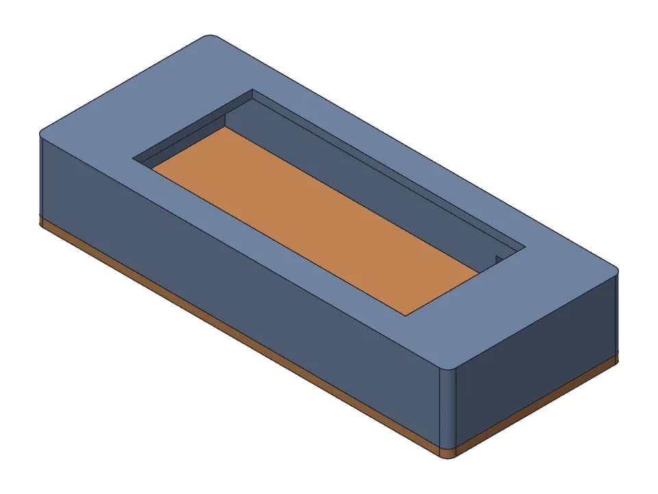
Both flat: the base stands on its floor as modelled, and the lid prints upside down, plate on the bed and snap arms pointing up (the downloads lay it out that way).
Supports
None
Material
PLA or PETG. The snap strain was checked against a PLA limit.
Layer height
0.2 mm
Hardware
1 x ESP32-DevKitC V4 board (not printed)
Time and filament
About 1 h and 22 g at the default size: a rough estimate from the model's volume and surface (PLA, 15% infill, about 1 mm of walls, 0.2 mm layers), not a slicer.
  • Measure how far your header pins stick out under the board, plastic spacer included, and set the space under the board a little higher than that. The pin length was not modelled.
  • Try your USB cable in the opening before closing the lid. Its bottom edge is only 0.5 mm below the top of the board, so a plug with a thick moulding may stop short. Use a slim plug, or ask the designer to lower the opening.
  • Lay the board on the ribs with the USB end at the opening, then press the lid straight down until both arms click. To open it, press the two hooks in through the windows in the long walls.
  • The snap fit (0.27 mm hooks) is checked on the model only. Print both parts once and try it before relying on it.

How it was designed

Designed with buildcad's AI agent, checked by the buildcad team. This is the request it started from and an edited account of what it did (more on how text to CAD works).

The request

An enclosure for an ESP32-DevKitC V4 dev board with the USB port accessible and a snap-on lid.

  1. 1

    It read the board drawing

    The agent loaded the DevKitC V4 entry of the parts library, from Espressif's dimension drawing: a 48.26 x 27.94 mm board with no mounting holes, the micro-USB centred on one short edge, and the antenna overhanging the other by 6.04 mm. With no holes to screw into, it planned two ribs under the board and blocks beside it.

  2. 2

    Checks first

    Its checks: the board inside the base with no overlap, the closed lid clear of the base, an inside length of 57.3 mm (board, antenna and two 1.5 mm end gaps), an inside width of 33.9 mm with 3 mm beside the board for the snap arms, and a clear path through the USB opening.

  3. 3

    First build

    Base, lid and a board stand-in built at once, and every check passed: 57.3 x 33.94 mm inside, 61.3 x 37.94 x 19.1 mm for the base. The assembly check pushed the lid on over 14 mm with no collision, 1.5 mm from the board, and found a snap strain of 0.61% against a 1.0% limit for PLA on both arms.

  4. 4

    Every slider extreme

    After a section view, the agent ran the slider sweep: all 12 extremes built as valid single bodies, and the assembly was checked again at each one with no collision. Under 1% of the base's surface counted as overhang.

  5. 5

    What it left to the maker

    Its reply says the case was not test-printed, that it assumed the header pins point down (9 mm of room under the board), that clone boards differ, and that there are no cut-outs for the EN and BOOT buttons.

One run of the agent: 2 min 10 s, about $0.29 of model time at list price (claude-sonnet-5-5). The model code behind this page is the code it wrote, unchanged.
Change it with AI

Set the sliders, then press Change it with AI: a copy goes to your designs at those sizes and the designer opens with a suggested change you can edit. Its changes use credits like any design; new accounts start with free ones.