BuildCAD AI

Battery wall mount, customizable: set the rail width for your 18 V pack

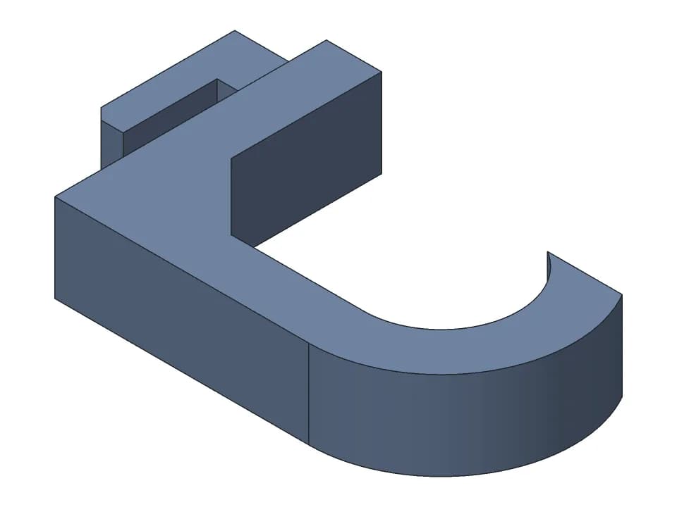
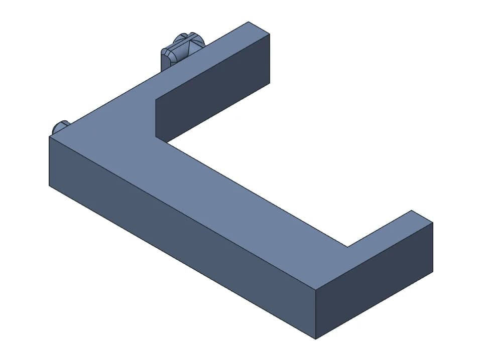
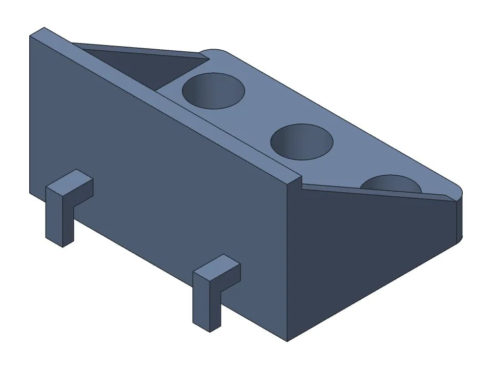
A wall mount for 18 V slide-on power tool packs, such as M18 or 20V MAX style batteries. Two T-shaped rails take the pack's side channels, a stop at the bottom holds it, and two countersunk screws fix it to a wall or a board. At the defaults it is 87 x 90 x 15 mm, with 75 mm across the rail lips. Set the rail width (40 to 120 mm), the fit clearance, the rail length and height, the lip shape and the screw size (M3, M4 or M5).

Customize Change it with AIFree STL, 3MF and STEP, no accountMeasured on the model

Parameters

Wall screw size

Rail width (across both lips)mm
Fit clearance per sidemm
Rail lengthmm
Rail height above platemm
Lip overhangmm
Lip thicknessmm
Rail stem thicknessmm
Back plate thicknessmm
Plate margin beside railsmm
Bottom stop thicknessmm

Sliders and downloads are free. Changes by the AI designer use credits like any design; new accounts start with free ones.

It prints with the wall side flat on the bed and no supports, since the lip undersides are cut at 45 degrees. The rail profile is an assumption, not a brand drawing, and no pack was measured. Measure the channels on your battery, set the sliders, and print a short rail to check the slide before the full mount. The pack's latch is not modelled: the battery is held only by the stop and its own weight, so mount it with the stop at the bottom.

Parameters

Every slider in the viewer above, with the range the model accepts. The model rebuilds valid at both ends of each range.

ParameterRangeDefaultWhat it changes
Rail width (across both lips)40 to 120 mm75 mmOverall width across the outer tips of both lips, before the fit clearance. Measure it on your pack's channels.
Fit clearance per side0 to 0.8 mm0.3 mmTaken off each side of the rails so the pack slides on. Raise it if the slide is tight.
Rail length50 to 200 mm90 mmLength of the rails and the plate along the slide.
Rail height above plate8 to 16 mm9 mmHow far the top of the rails stands off the plate. Match it to the depth of your pack's channels.
Lip overhang1.5 to 5 mm3 mmHow far each lip sticks out sideways past its stem, into the pack's channel.
Lip thickness2 to 4 mm3 mmThickness of each lip at its outer tip.
Rail stem thickness3 to 8 mm4 mmThickness of the upright wall under each lip.
Back plate thickness5 to 12 mm6 mmThickness of the back plate, which is also the depth of the countersunk screw holes.
Plate margin beside rails4 to 20 mm6 mmPlate width beside each rail. A wider margin gives a bigger plate against the wall.
Bottom stop thickness5 to 25 mm10 mmLength of the stop block at the bottom end that the pack rests on.
Wall screw sizeM3, M4, M5M4Size of the 2 countersunk wall screws. The holes and countersinks follow it.

Proof: measured on the model

What the design must satisfy and what our CAD engine measured on the model at the default values. Only measured values are shown here; nothing on this page has been printed by us yet.

RequirementWantedMeasured
Width across the rail lips (75 mm minus 0.3 mm fit per side)74.4 mm74.4 mm
Lip overhang on each side, past the rail stem3 mm3 mm
Countersunk holes for M4 screws (4.5 mm clearance)2 holes2
Total thickness off the wall (6 mm plate plus 9 mm rails)15 mm15 mm
Rail length90 mm (the slider)90 mm
  • valid solid, one body, 87 x 90 x 15 mm, fits a 256 x 256 x 256 mm printer; overhangs: 0.0% of surface would need support.

Print notes

Orientation
Wall side flat on the bed, rails up, as modelled.
Supports
None
Material
PETG for a garage or shed, where it can get warmer than PLA likes; PLA indoors
Layer height
0.2 mm
Settings
4 walls and 30% infill or more, since the lips carry the pack
Hardware
2 x M4 countersunk screws (M3 or M5 if you change the Wall screw size option)
Time and filament
About 1 h 40 min and 35 g at the default size: a rough estimate from the model's volume and surface (PLA, 15% infill, about 1 mm of walls, 0.2 mm layers), not a slicer.
  • Measure your pack's channels first, then print a 50 mm rail (the shortest setting) to check the slide. Adjust Fit clearance per side, Lip overhang and Rail height until the pack slides on snugly.
  • Drive both screws before the battery goes on. They sit on the centreline, in the open space between the rails.
  • Mount it with the stop at the bottom and slide the pack down from above. There is no latch, so do not mount it sideways or where it gets knocked.
  • Holding strength was not tested.

How it was designed

Designed with buildcad's AI agent, checked by the buildcad team. This is the request it started from and an edited account of what it did (more on how text to CAD works).

The request

A wall mount for an 18 V slide-on power tool battery pack (about 75 mm wide rails), screws to the wall with two countersunk screws. Rail width adjustable.

  1. 1

    It assumed a generic rail profile

    Without a brand drawing, the agent assumed two T-shaped rails that the pack's side channels ride on: lips 3 mm deep and 3 mm thick, rails 9 mm off the plate, 75 mm across the lip tips with 0.3 mm taken off each side for fit. It did not look up a brand's profile.

  2. 2

    Checks before the model

    It wrote its checks first: 74.4 mm across the lips, 2 countersunk holes of 4.5 mm for M4 screws, and 15 mm total thickness off the wall.

  3. 3

    One build, every check in range

    The first build came out as one valid body, 87 x 90 x 15 mm, with all checks in range. The 45 degree lip undersides left 0 mm2 needing support, and the same run rebuilt all 20 slider extremes as one valid body each.

  4. 4

    What it left to the maker

    Its reply says the profile was not checked against a real pack and the latch is not modelled. It asks for a short test rail first, and offers to add a catch if you say where your pack's latch notch sits.

One run of the agent: 1 min 0 s, about $0.11 of model time at list price (claude-sonnet-5-5). The model code behind this page is the code it wrote, unchanged.